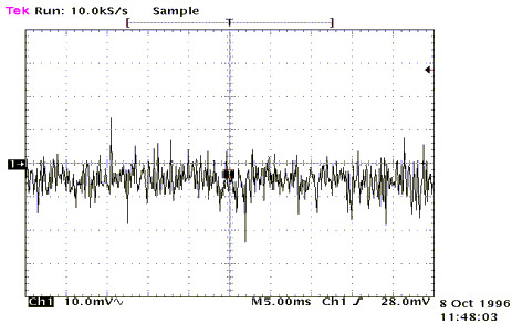
Most of the classical materials teach you to use separate power supplies and connect the digital ground (DGND) with the analog ground (AGND) in a single point. But is it sufficient ? No, it’s not, since you can have high frequency interference that propagates through the ground, from the digital circuits to the analog ones.
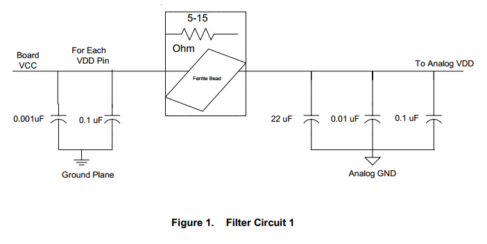
A good way for improving the isolation is to use an inductor for connecting the digital ground with the analog ground. At high frequencies, the inductor exposes a high impedance, basically isolating the two power rails. For DC, the inductor has a very low impedance, behaving like a wire.
Another important consideration is to use bypass capacitors on both power rails. Usually there is an inverse proportionality relation between the capacitance of a capacitor and it’s frequency response. For good results you should use ceramic capacitors for decoupling. They have a good frequency response. A common practice is to use more capacitors, of different sizes, a big one for lower frequencies and a small one for higher frequencies.
Recently I just came about a very interesting application note from Texas Instruments, which teaches you how to obtain a good separation of the power rails.
Below, you can see a circuit diagram from the application note describing the same practices:
This application note can be read here.


